The 3D Printed Electric Skateboard (With Genius Doug Smith)

STILL IN PROGRESS: CAD files will be available soon =).
Inspiration
Electric skateboards can cost up to $600-$700 for the most basic setups. Even if you have a DIY skateboard,
it's very difficult to build a quality electric skateboard without access to a machine shop or a couple weeks of work.
My hope with this was to build a high quality, reliable skateboard with only 6 hours of assembly for under $350. This reaches 18 mph.
This would require the useage of 3D printed parts, but the eskateboard community's pieces often broke, so I wanted to through my engineering hat into the ring and see if I could do better.
Basically, we built an electric skateboard that requires nothing more complicated than a 3D printer, a drill, and a soldering iron, common tools for hackers.
How does it work?
Note: A lot of this is reposted from my original 25mph electric skateboard. I think the circuit is the most important part about this, but it's basically a very simple timing-belt driven wheel.
Fix a pulley to the wheel and another one to the motor, and then have a belt that connects the two.
The mechanical part is pretty simple, except that you also need to somehow attach the motor to the skateboard axle.
You do this via a motor mount, which holds the motor in the air at a certain distance from the wheel pulley.
I think the circuit is the most important part about this, but it's basically a very simple timing-belt driven wheel.
Fix a pulley to the wheel and another one to the motor, and then have a belt that connects the two.
The mechanical part is pretty simple, except that you also need to somehow attach the motor to the skateboard axle.
You do this via a motor mount, which holds the motor in the air at a certain distance from the wheel pulley.
There are three ways of doing this:
- You can weld the motor mount to the axle. Best way, but lots of work if you don't have a welder.
- You can clamp the motor mount to the axle by screwing two pieces of aluminum around the axle as seen here . Sounds good, but it's expensive.
- You can drill through the axle and the piece of aluminum and hold it in place. Sounds like the best way, but this is actually horrible. Too many vibrations will break it quickly and too much work on assembly.
For this fast assembly iteration, I decided on the second option, clamping the motor mount to the axle. However, according to the eskateboard community, they break a lot. So I tried to fix those problems by using large three and a half inch screws that went through the entire 3D printed piece. They were in charge of reinforcing the motor mount to withstand vibrations, while also acting as the clamp to the actual axle.
Total Costs
| Specs | Cost | Link |
|---|---|---|
| ESC-6S | $51.90 | HobbyKing |
| Li-Po Battery | $23.45 * 2 | HobbyKing |
| 270Kv Motor | $53.40 | HobbyKing |
| Remote Controller | $18.35 | Ebay |
| Caliber Trucks | $35 | Amazon |
| Wheels | $28 | Amazon |
| Board | $37 | Amazon |
| BMS (This one might've been faulty) | $15 | Ebay |
| Timing Belt | $14.00 | Amazon |
| Spacers | $7.99 | Amazon |
| BESC programming card | $7.55 | Hobby King |
| Screws (1/4-20, 3 1/2" x 6), (10-32, 3 1/2" x 4), (2-56 set screws) and hex nylon lock nuts (1/4-20 x 6) | $5.00 at your nearest hardware store | Hardware store |
| A small plastic box | $3.50 at your nearest hardware store | Hardware store |
| XT-60 connectors | $8.99 | Amazon |
| Voltage checker | $6.99 | Amazon |
| 24V Battery Supply | $9.99 | Amazon |
| Total | $349.56 (PHEW!) |
Tools required
- Tap and Drill for 1/4-20, 2-56, and 10-32
- A hand-drill
- Countersink
- Soldering iron
- Electrical tape
The Circuit
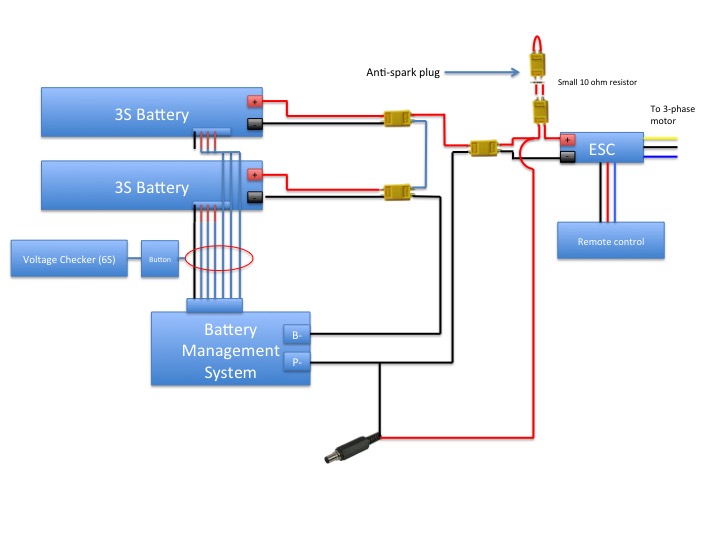 Now let's talk about the circuitry. You have a 3S (12V) battery that you connect in series with another one, to make it 24V.
Then you use an Electric Speed Controller (ESC) specced for 6S batteries and ~60A, to control the speed of a motor that is also specced for a 6S motor and runs at 60A.
We use a remote control that interfaces with the ESC to control the speed of the motor.
Now let's talk about the circuitry. You have a 3S (12V) battery that you connect in series with another one, to make it 24V.
Then you use an Electric Speed Controller (ESC) specced for 6S batteries and ~60A, to control the speed of a motor that is also specced for a 6S motor and runs at 60A.
We use a remote control that interfaces with the ESC to control the speed of the motor.
You then buy a Battery Management System (BMS) that is also specced for 6S and a discharge rate of ~45A and a pulse rate of at least 60A. The Battery Management System allows you to charge the LiPo batteries one cell at a time, which increases lifetime and prevents the battery from bursting into flames. Having an internal BMS also allows you to easily charge the battery with just a DC jack rather than using conventional methods of charging each 3S battery separately with a balance charger.
To check the battery level, we have a voltage checker which reads out the voltage of the individual batteries. This allows us to continuously check that the BMS is working, but because we don't always want to check, we have a button that we press to turn it on.
Lastly, we have an anti-spark plug that turns on the ESC. The anti-spark plug catches the spark that happens with you connect a high voltage to a free line. If you don't suppress the spark, the connection with begin to oxidize and it'll eventually oxidize to the point of high resistance and difficulty plugging in and out. We use two XT-60 connectors, one that connects with a 10ohm resistor, and the other that is free. The 10 ohm resistor catches the spark, and then plugging in the other XT-60 allows for the circuit to take the path of least resistance away from the 10ohm resistor.
Design decisions
Actual Skateboard
I bought Caliber trucks, which are incredibly high quality trucks for the price. They have rectangular axles, which allow for you to clamp the motor mount on them.For the board, we bought this. Doug definitely wanted something cooler, but because we were price constrained, we chose something cheap.
Motor, Batteries, and ESC
I used this to to figure out I needed a solid 18mph ratio (you can use an efficiency of 60%). I added 6S batteries on a 270 kV motor, with a 28-teeth small pulley and a 56-teeth large pulley (reasons for that explained later).I used that particular ESC because it was the cheapest and most versatile high voltage ESC for its price. Because the discharge of the motor was maxed at 60A, but ESCs have a tendency to break very quickly, I overspecced for 100A. It worked like a charm.
Belt Decisions
I chose GT3 belts because backlash upon stopping is better than the trapezoidal timing belt system in HTD belts. I chose GT3 instead of GT5 because the load is spread more across the entire pulley, which is essential for 3D printed parts, and there were cheap GT3 Boosted Belt replacement belts that we used. I needed to maintain a reasonable distance between the large pulley and the small pulley, which ended up being a mere 7mm. Problems occurred later with the shaft of the motor interfering with the wheel, but we fixed that. Use this website to help with calculations.Battery Management System and Voltage Checker
We got this beeper to give us accurate battery measurements. The BMS we bought might've been faulty, because when we plugged in our batteries, they were discharging rapidly. We still have to figure out the issue.Motor Mount
The motor mount went through a lot of iterations. We eventually ended up with the one you can see below.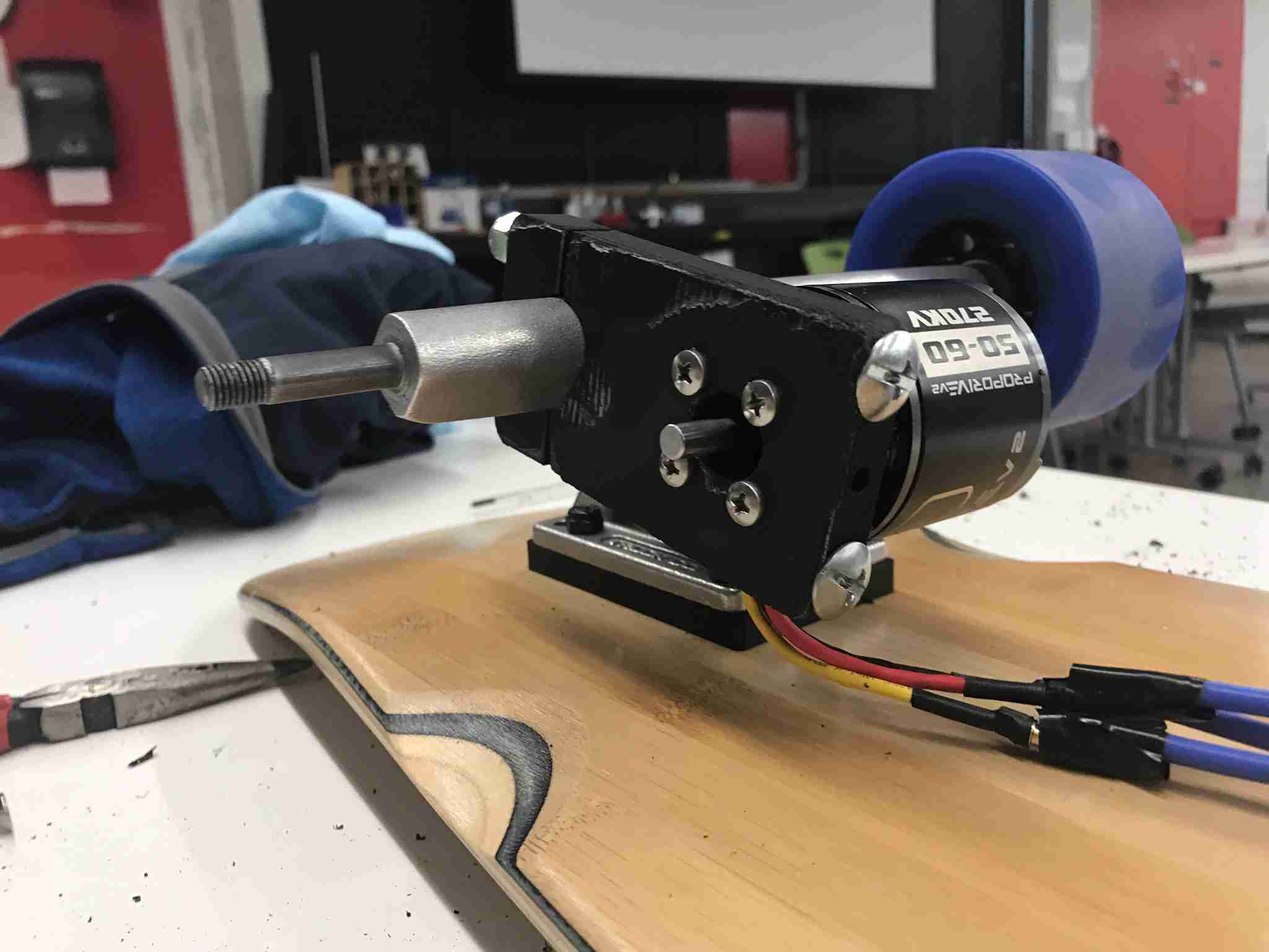
The idea was to strengthen the mount against vibrations. We cut two tight fit holes in the larger half of the motor mount and then one tapped hole in the smaller half. Then, we tapped the smaller half with a 1/4-20 tap and used a clamping mechanism. In essence, we use the versatility of 3D printing while enfusing it with the strength properties of the steel. Vibrations of the motor are now securely transferred to the axle, and vibrations different terrain cannot break the 3D print as it would also need to bend the steel screw.
Remote Controller
I used this very simple and durable remote controller. Those that were meant for RC cars were too bulky, but this one was just perfect. It also used adaptive frequency hopping, which was very helpful. Do not use the NRF24L01 for reliable and on-time data transmissions.Power Supply for Battery Charging
You can easily find these power supplies lying around, but I provided a link to be sure. You should technically go up to 25.2V for LiPo batteries to maximize the battery, but I couldn't find one in the price range we wanted. In all honesty, going through a garage sale will probably land you a solid 25.2 or 24V power supply very easily. The difference per cell is also only .2V per cell, which is around a 10% reduction in battery life.Building the actual skateboard
Putting together the skateboard
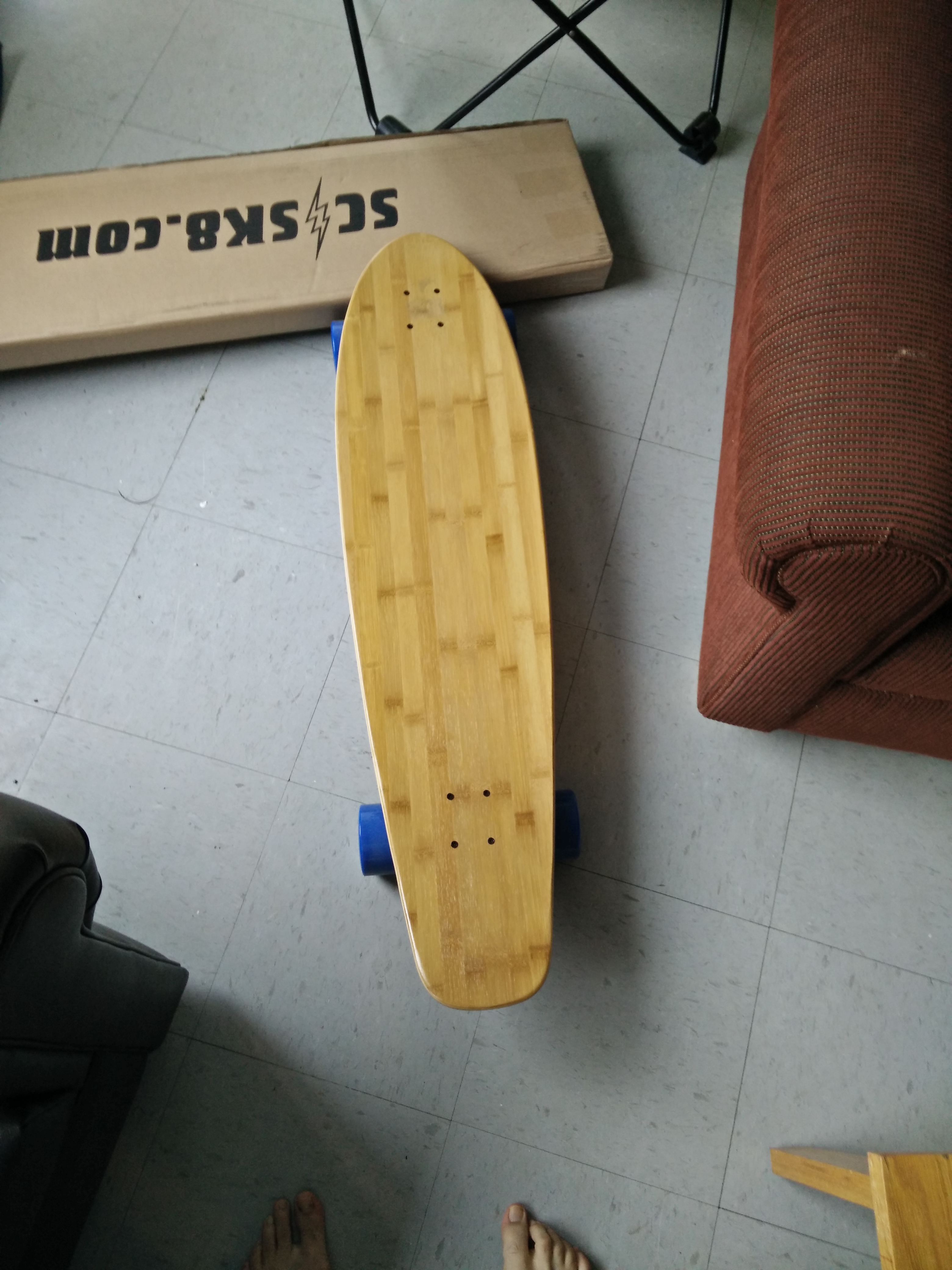 The skateboard build itself was very similar to what I had done in my previous skateboard build, but we just used better Caliber trucks this time and we didn’t use flywheel clones. The real flywheels were definitely of better quality than the flywheel clones. I would recommend investing in those.
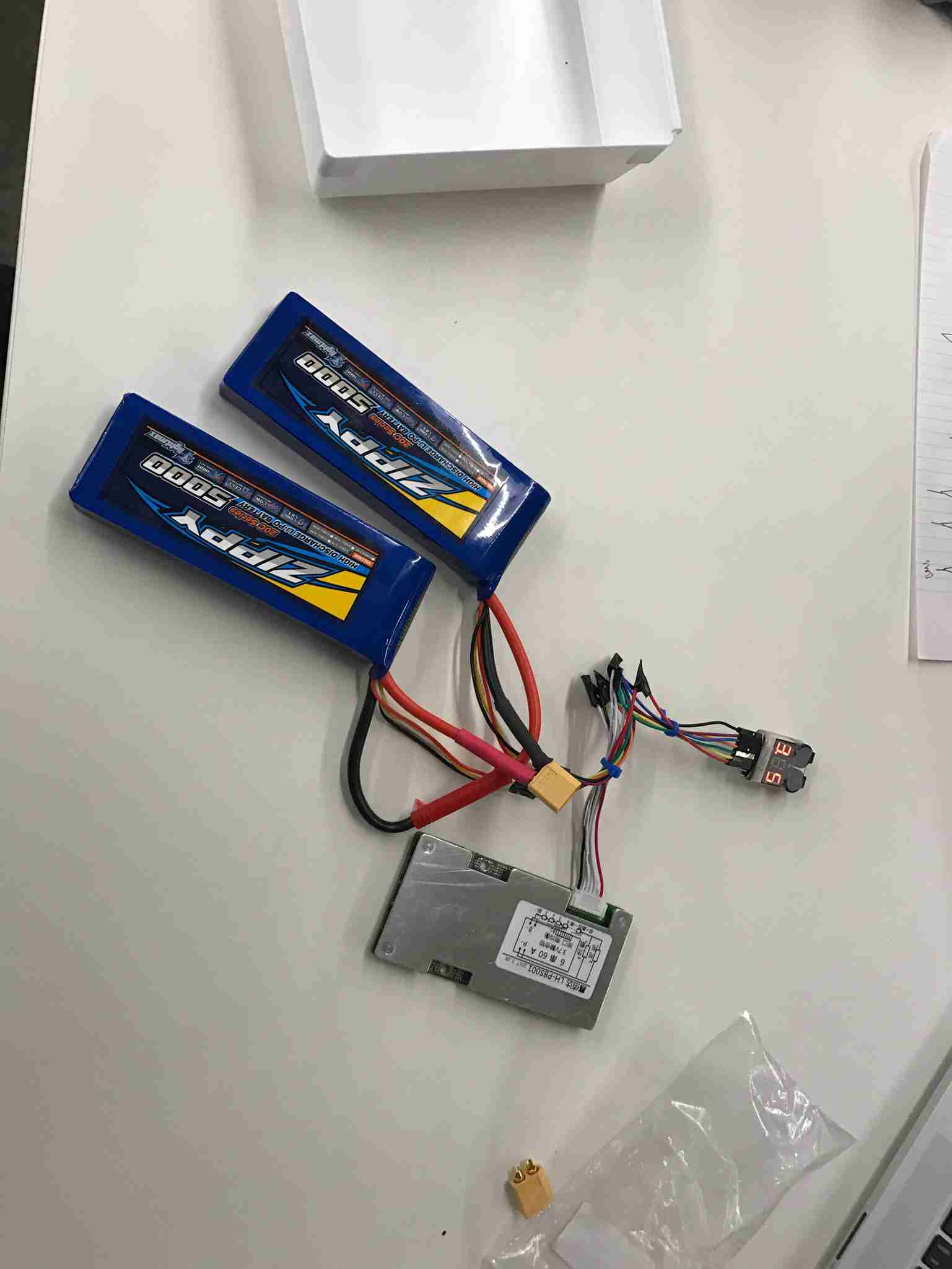
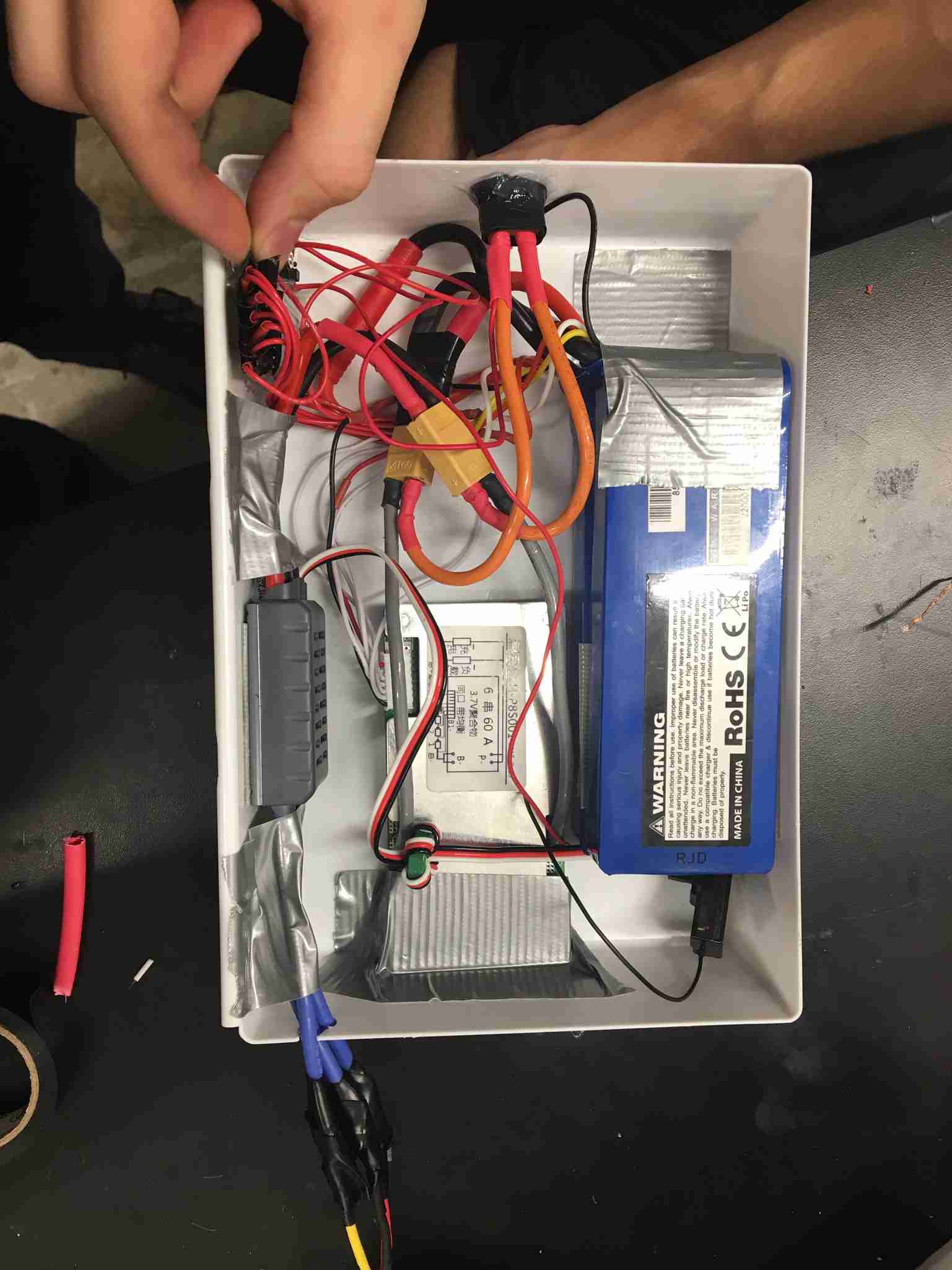
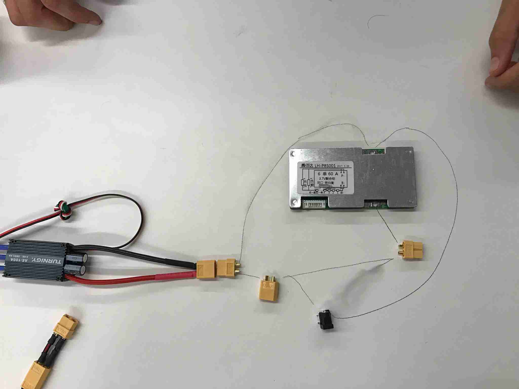 We laid out what was necessary to connect on a table, figured out which connectors would go where, and then went ahead with soldering connections to the XT-60 connectors.
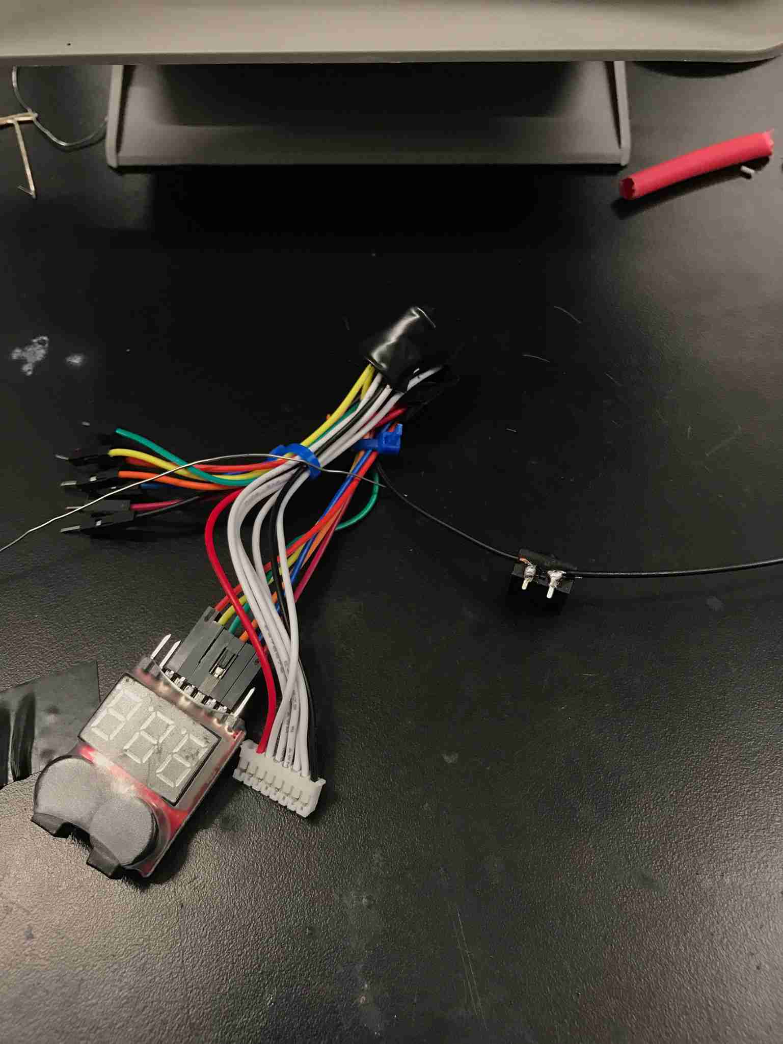 We used jumper cables to connect the balance wires together, and then a button to connect the ground to turn on the voltage checker.
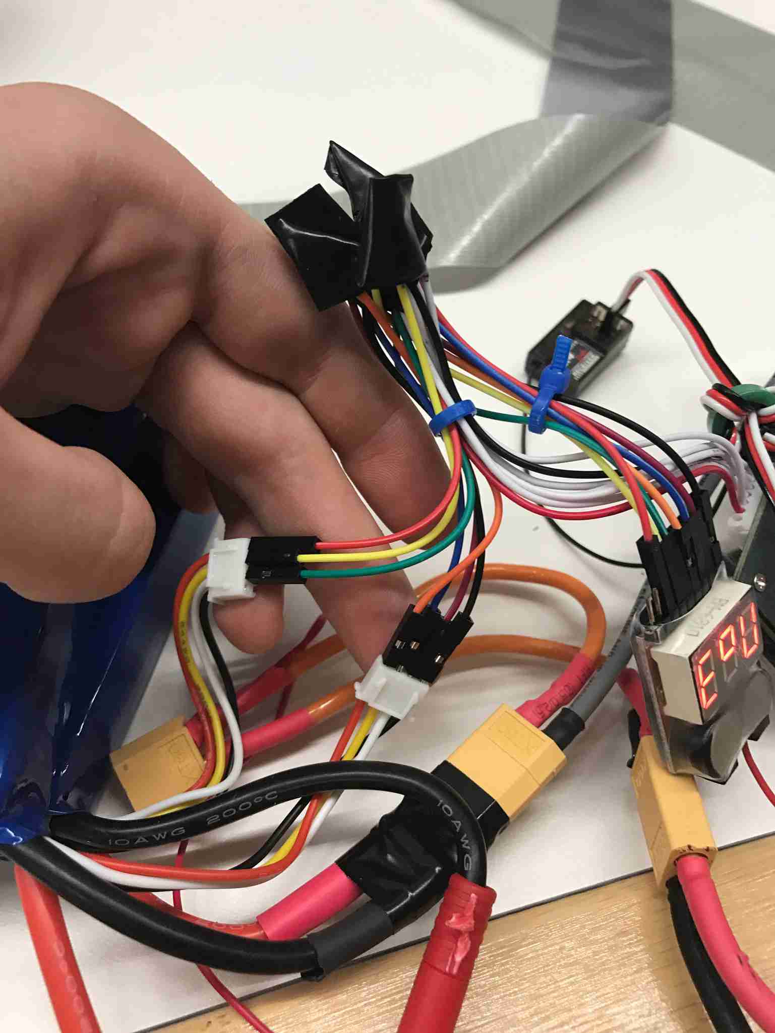 Then we connect the balance wires to the battery itself.
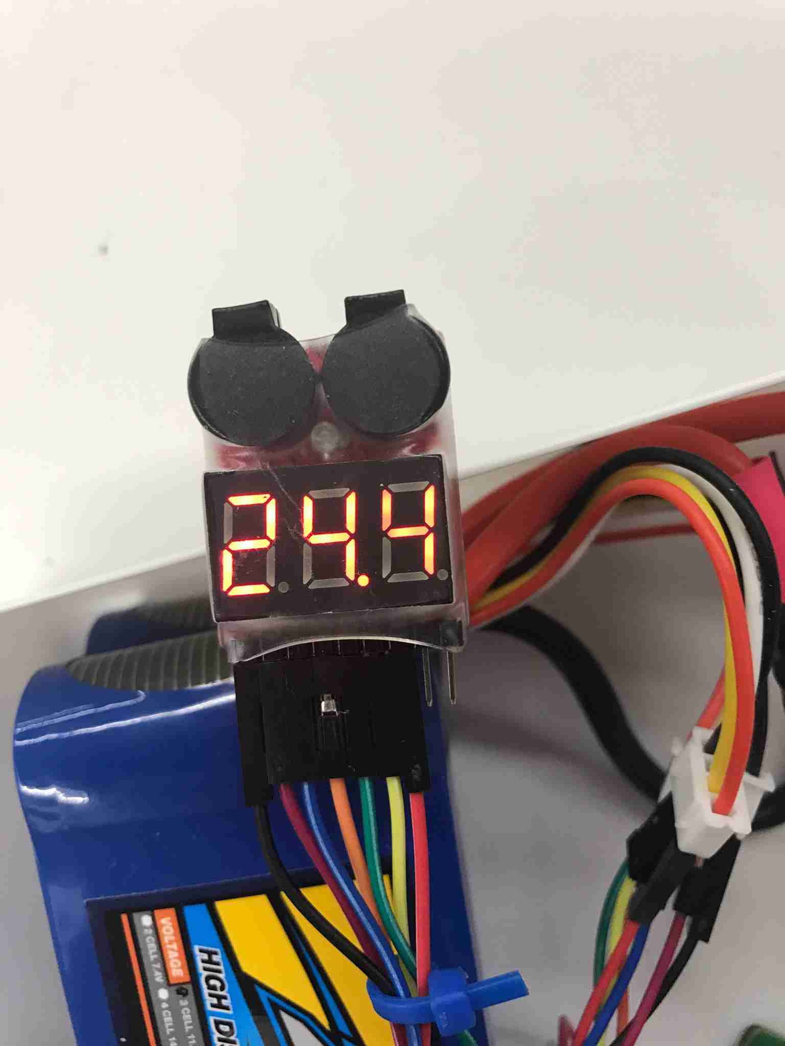 Testing the battery voltage checker. We got 24.4V! Solid battery level displayed
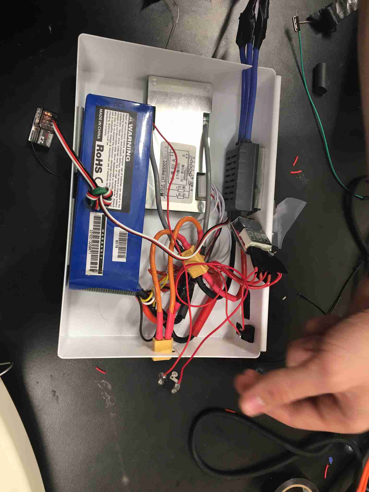
 We then connected the balance wires to the BMS.
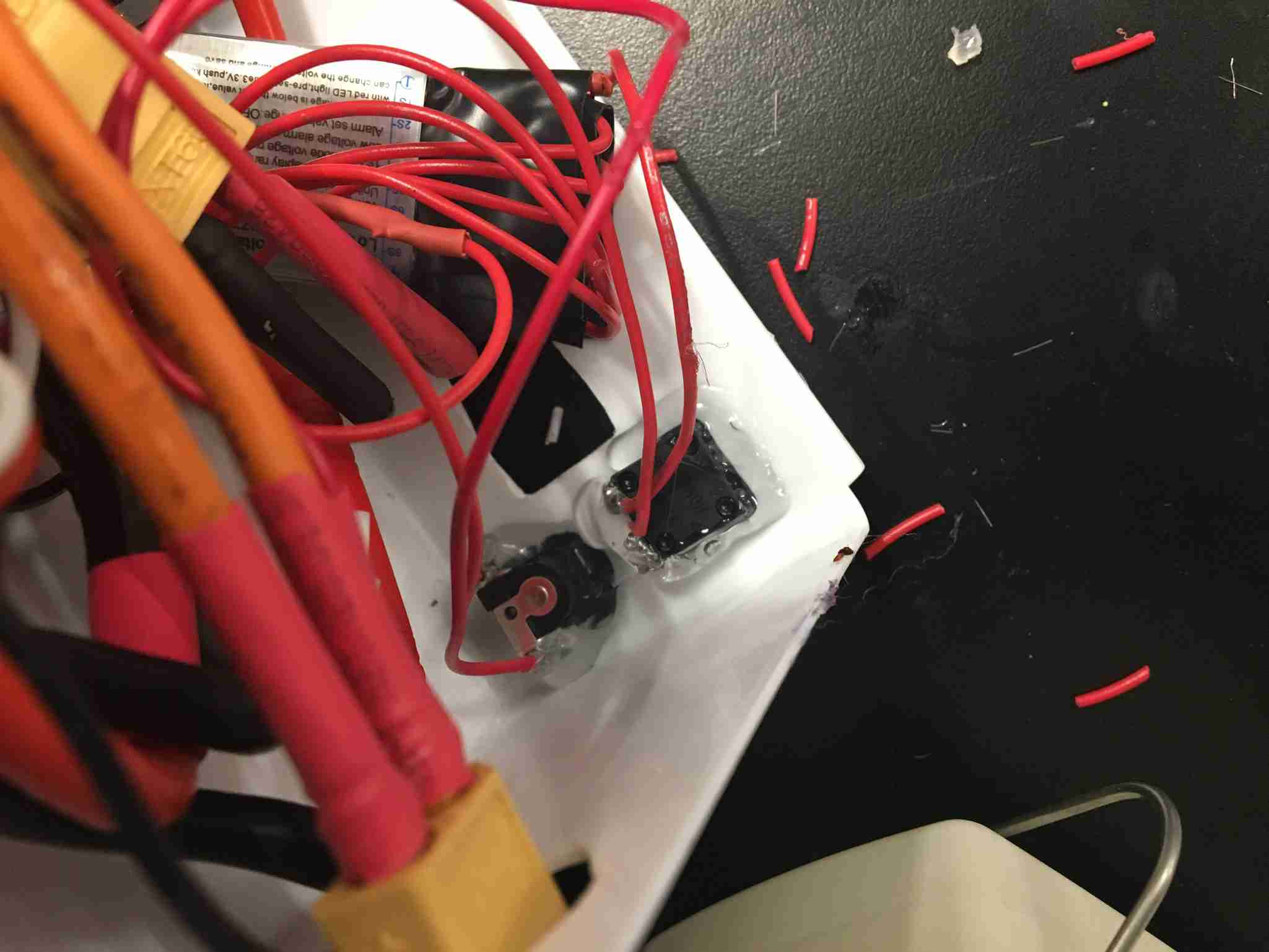
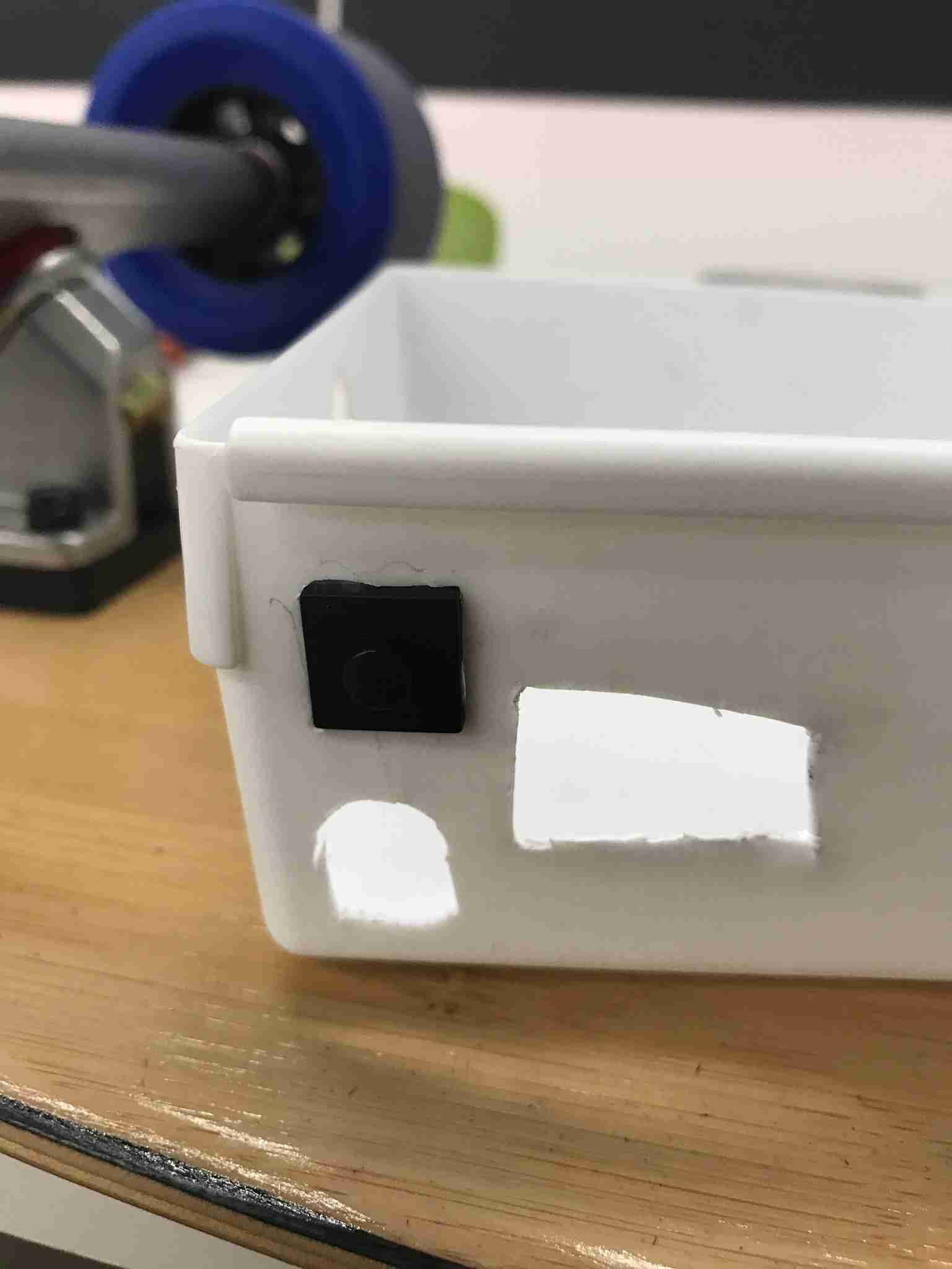 Then, we cut holes in the box we bought for the interfacing (DC plug for charging, button to test battery voltage, battery voltage display, and anti-spark plug)
 Ensuring the DC plug fits well.
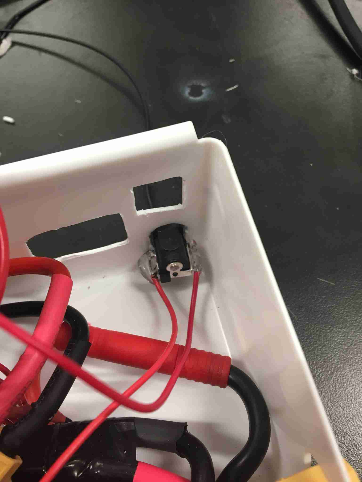
 Hot glue on the inside to hold everything in place
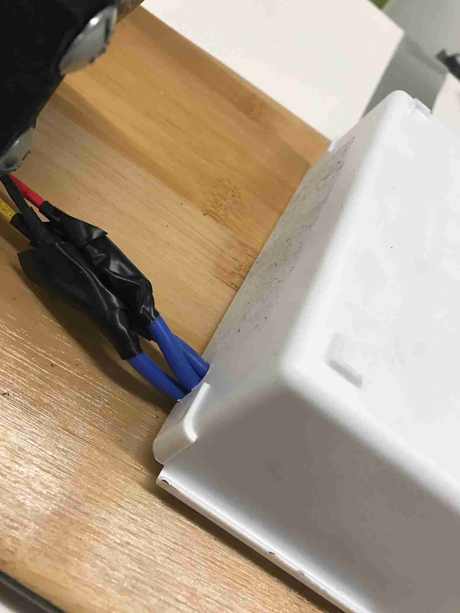 We also cut a small hole for the wires going to the motor.
 We used duct tape to hold wires and different components in place.
 Then we added the remote control in (the wire connecting to the module on the top left). That module would talk to the remote control and would write a PWM signal to the ESC depending on how hard I pulled the trigger, which would dictate the speed of the ESC. To set up the remote control, plug the binding plug into the receiver, hold “connect” on the remote controller, and then it should connect. Then remove the binding plug.
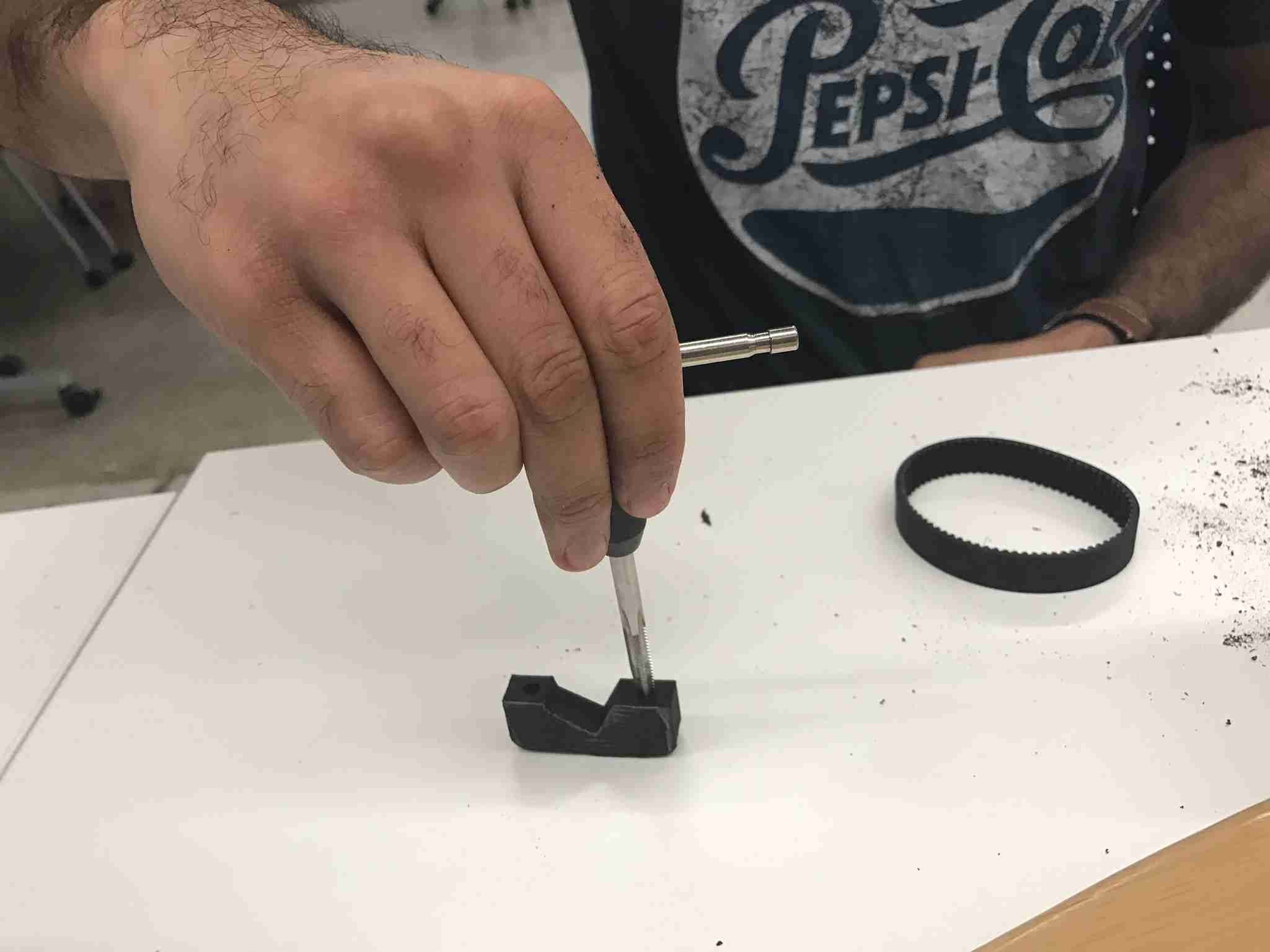
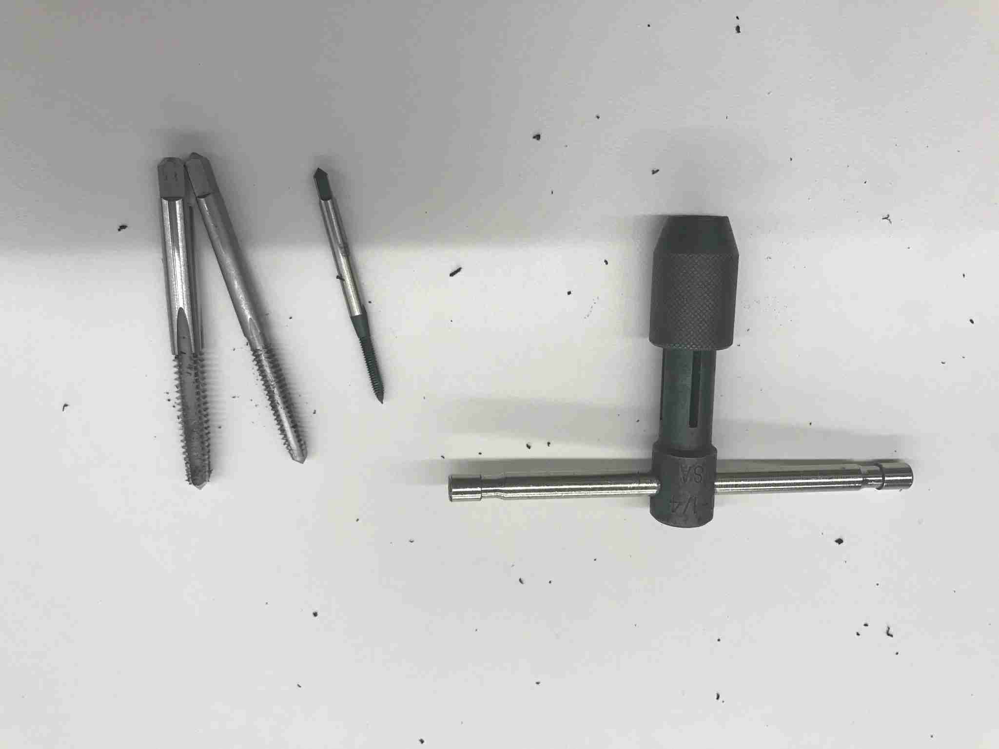 Then came the actual tapping of the 3D parts. We had one ¼-20 and one 10-32. ALWAYS screw the tap past its tip. Otherwise, you’ll just be tapping it when you drill in the screw, and with fragile 3D printed parts, you’re likely to pull apart the layers of the print.
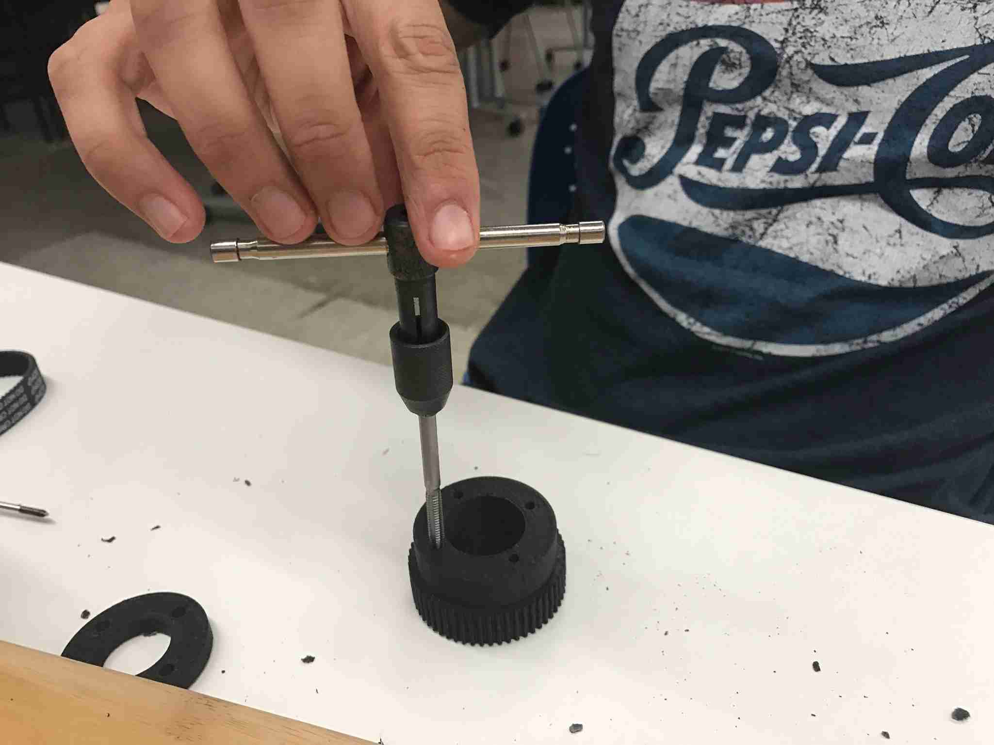 Tap the large pulley with the 10-32, and be sure to go all the way through. Your tap should be just long enough to go all the way through.
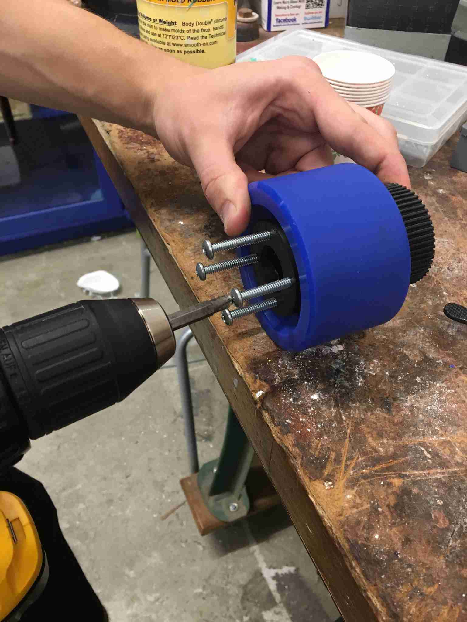 Then you use the washer we have and align the motor mount on the other side (Make sure you align them correctly! These holes are not aligned in a square fashion, but rather a rectangular one in order to press against the corner of the inside of the flywheels). Drill through.
 It should fit like such. If you messed up your 3D print, it’ll look very much like this image, where the piece is slightly morphed. If this is the case, then the bed of your 3D printer was most likely not warm enough, or the way you placed the .stl files in the bundle was too far apart. Try to keep everything in the center of the bed.
 Tap the smaller part of the motor mount with the ¼-20.
Screw the motor in place now.
Tap the smaller part of the motor mount with the ¼-20.
Screw the motor in place now.
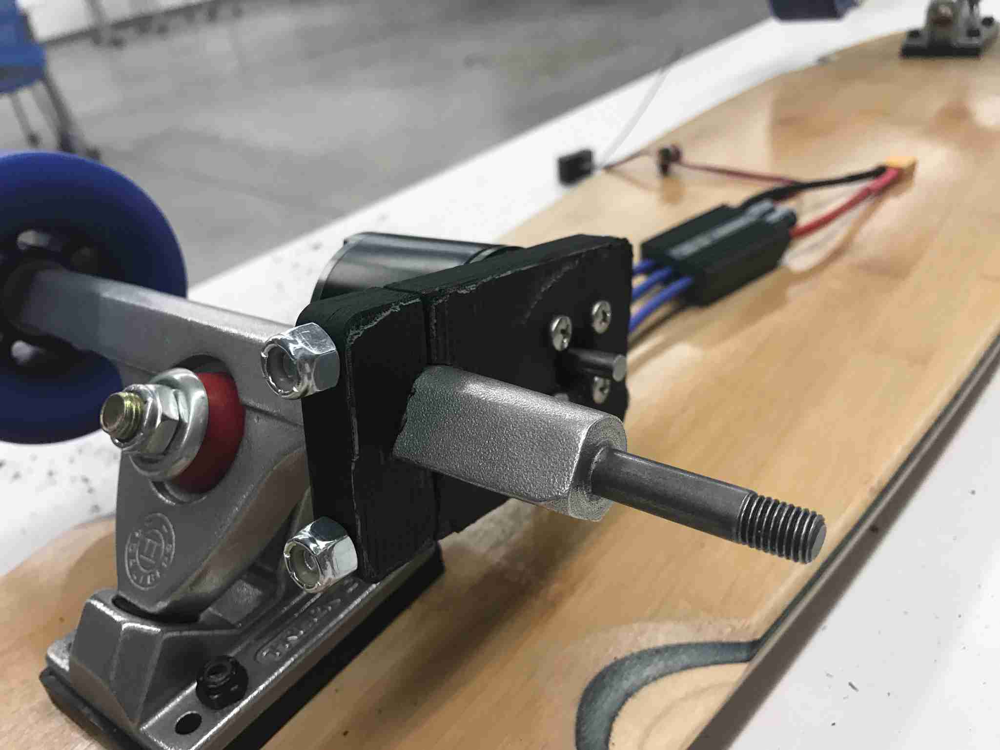
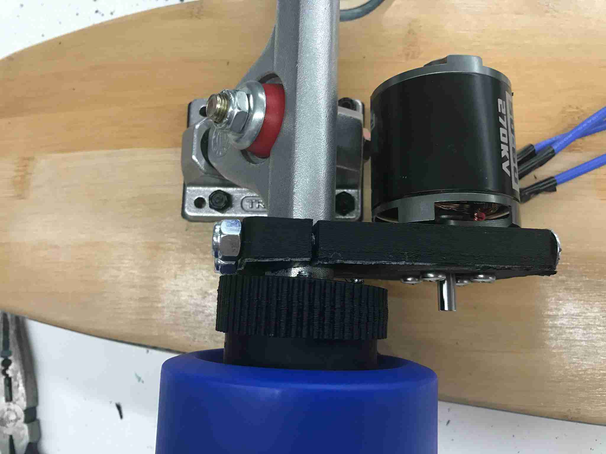
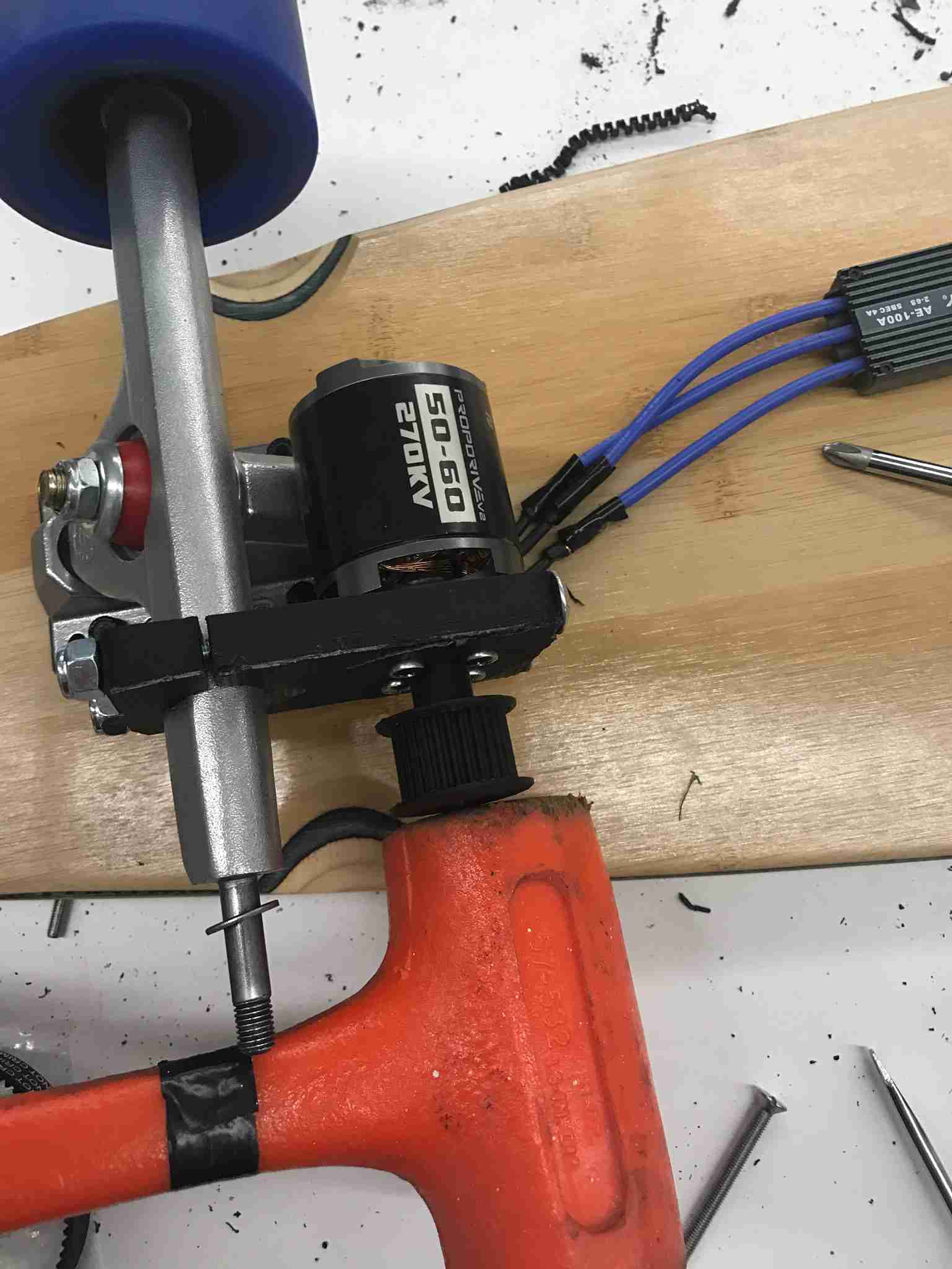 This wasn’t how we ended up using the motor pulley. This version is too brittle. The final version actually extended the shaft using a part given with the motor. However, this should give an idea of where the small pulley goes.
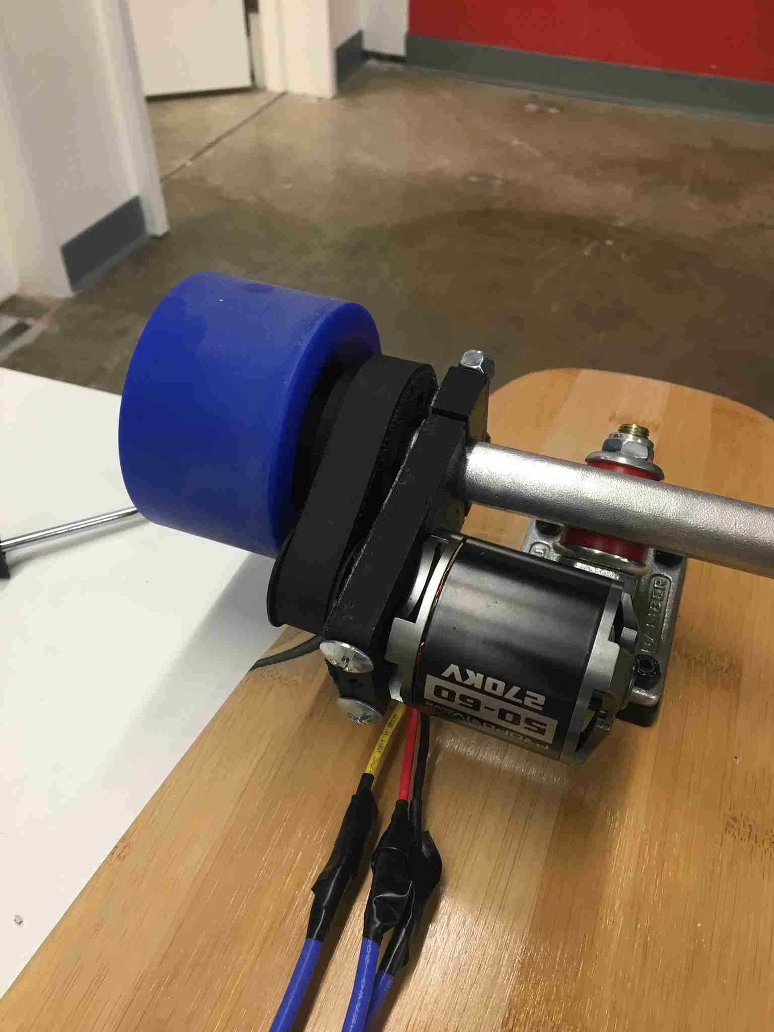 In general, you should insert the small pulley first, then attach the belt, then push the wheel onto the belt (turning the wheel while you’re trying to squeeze it on will help a lot).
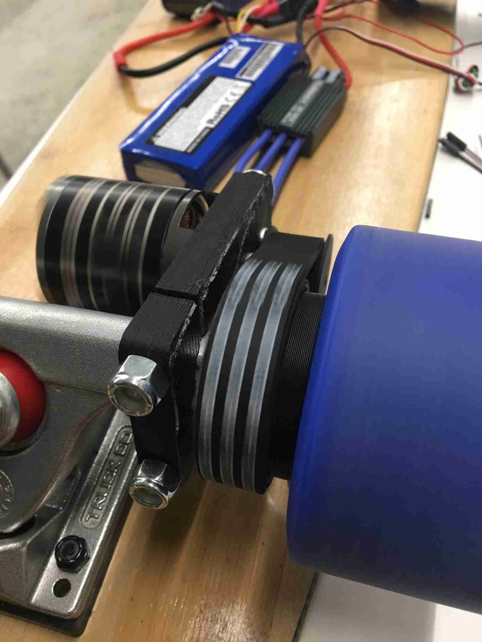 Now you can code up the ESC and plug it into your circuitry to see if the motor runs. The instructions for how to code the ESC are on the programming card.
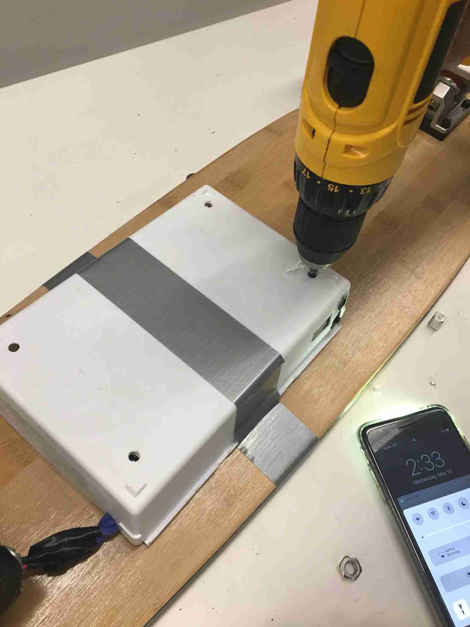 After we had everything placed where it should be, we placed the box where we wanted it to go, and then drilled through to the skateboard to leave a small notch (first we just drilled a small hole in the plastic case, and then ensured we weren’t drilling through any wires when we drilled through the skateboard.
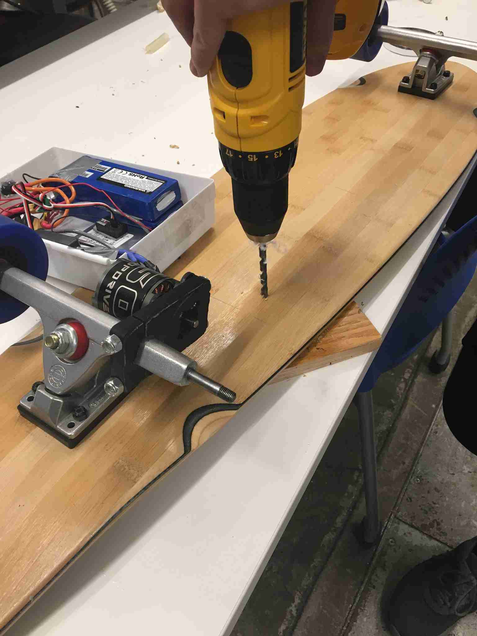 Then we drilled through the skateboard. We screwed up here, because it stripped the wood out on the other side. We should’ve placed tape around the hole on the other side, and then drilled through.
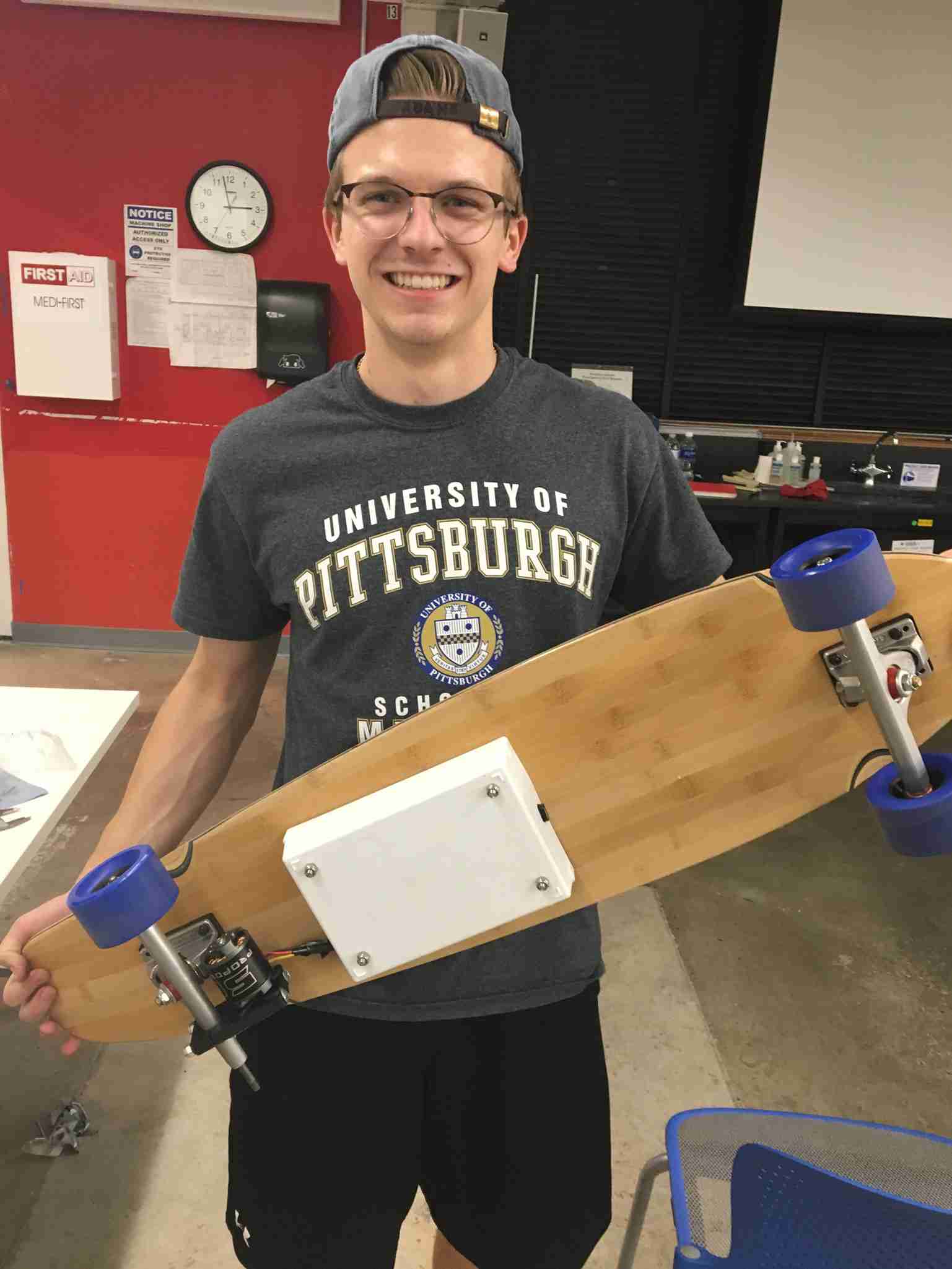 Then you squeeze your last four ¼-20 screws through the holes of the board and of the box, and then use your nylon nuts to secure the casing to the board.
And then you’re done! This is Doug with his sexy new skateboard.
Then you squeeze your last four ¼-20 screws through the holes of the board and of the box, and then use your nylon nuts to secure the casing to the board.
And then you’re done! This is Doug with his sexy new skateboard.